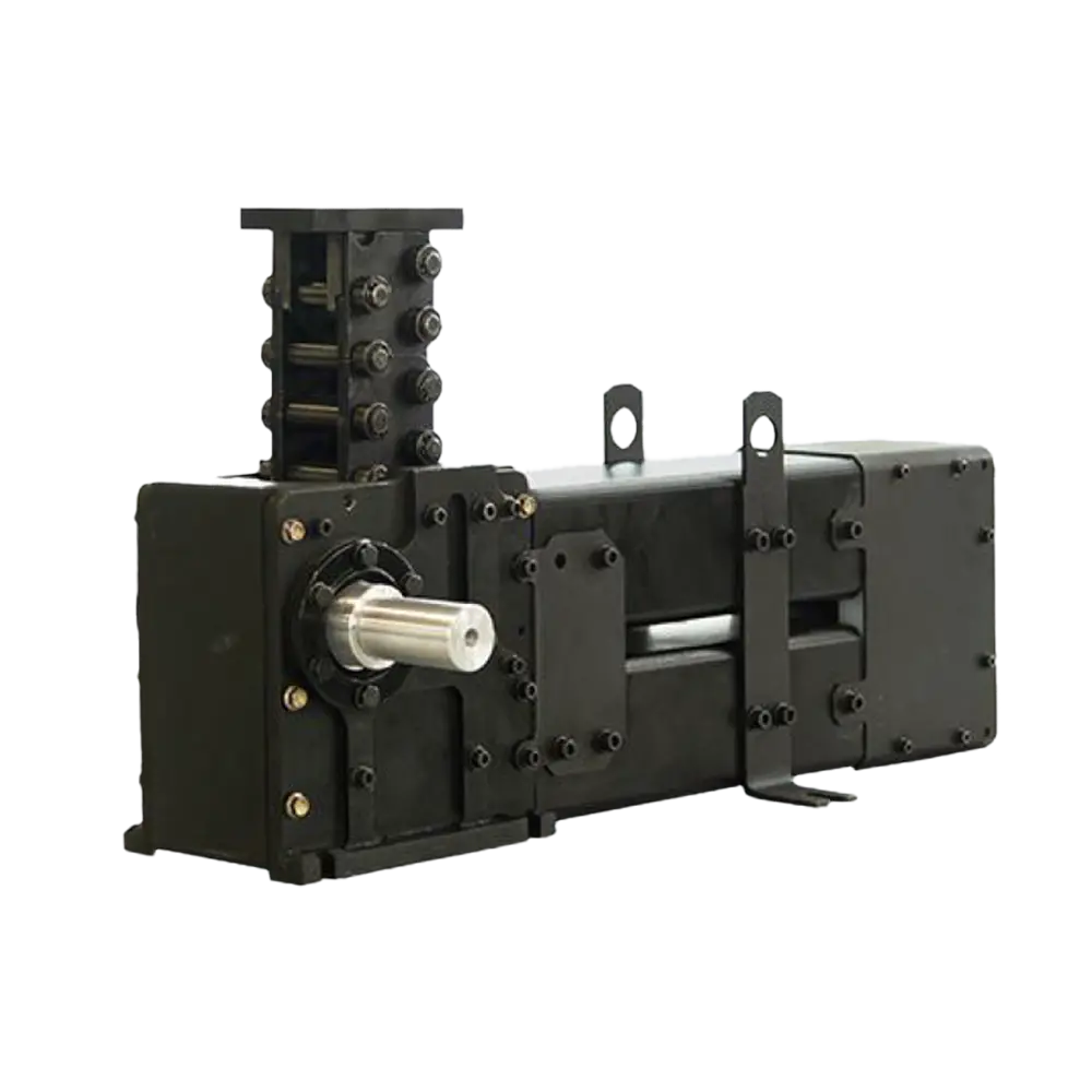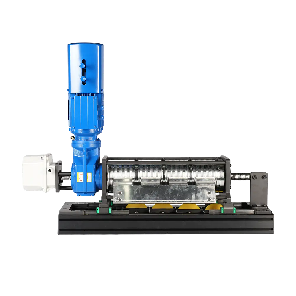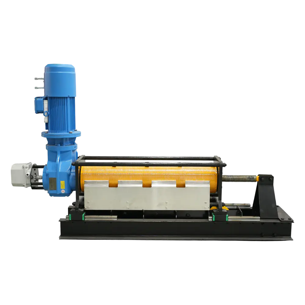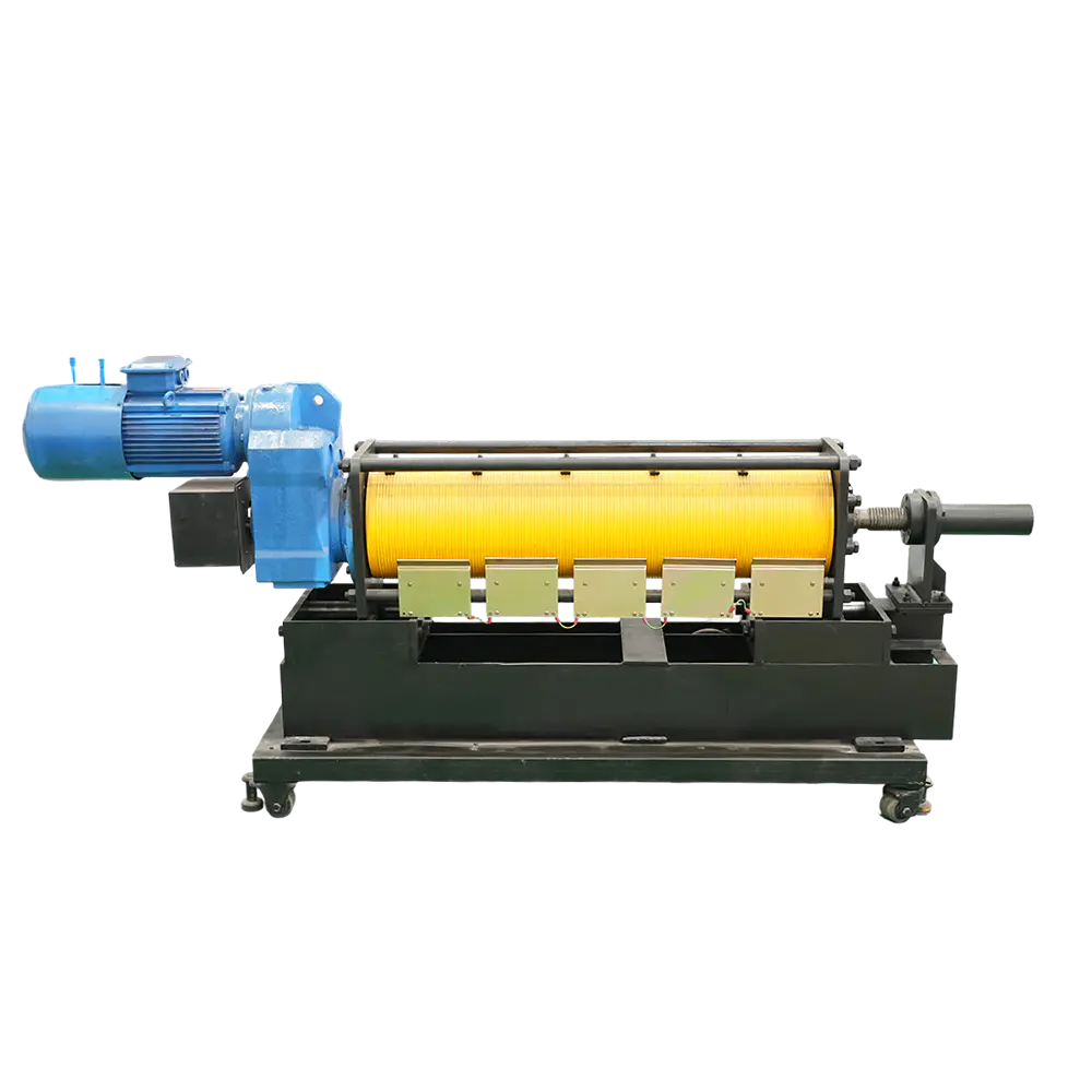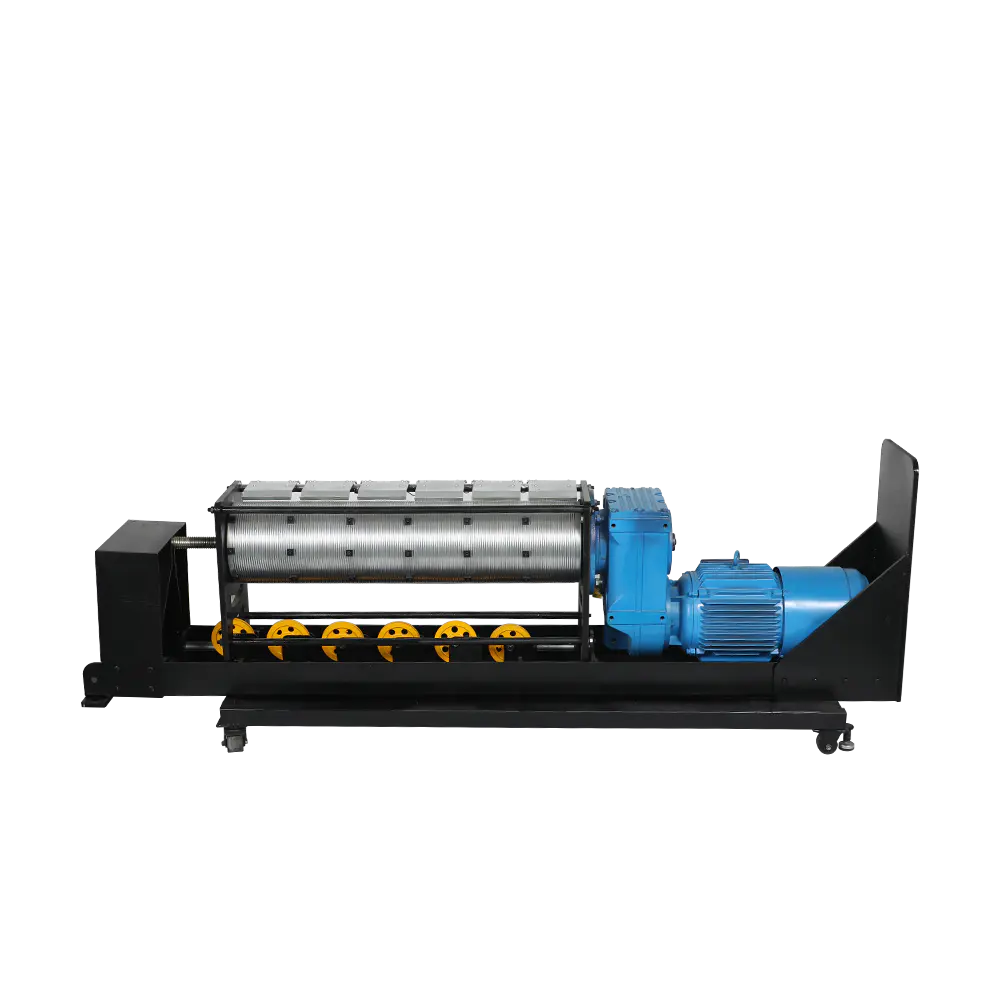
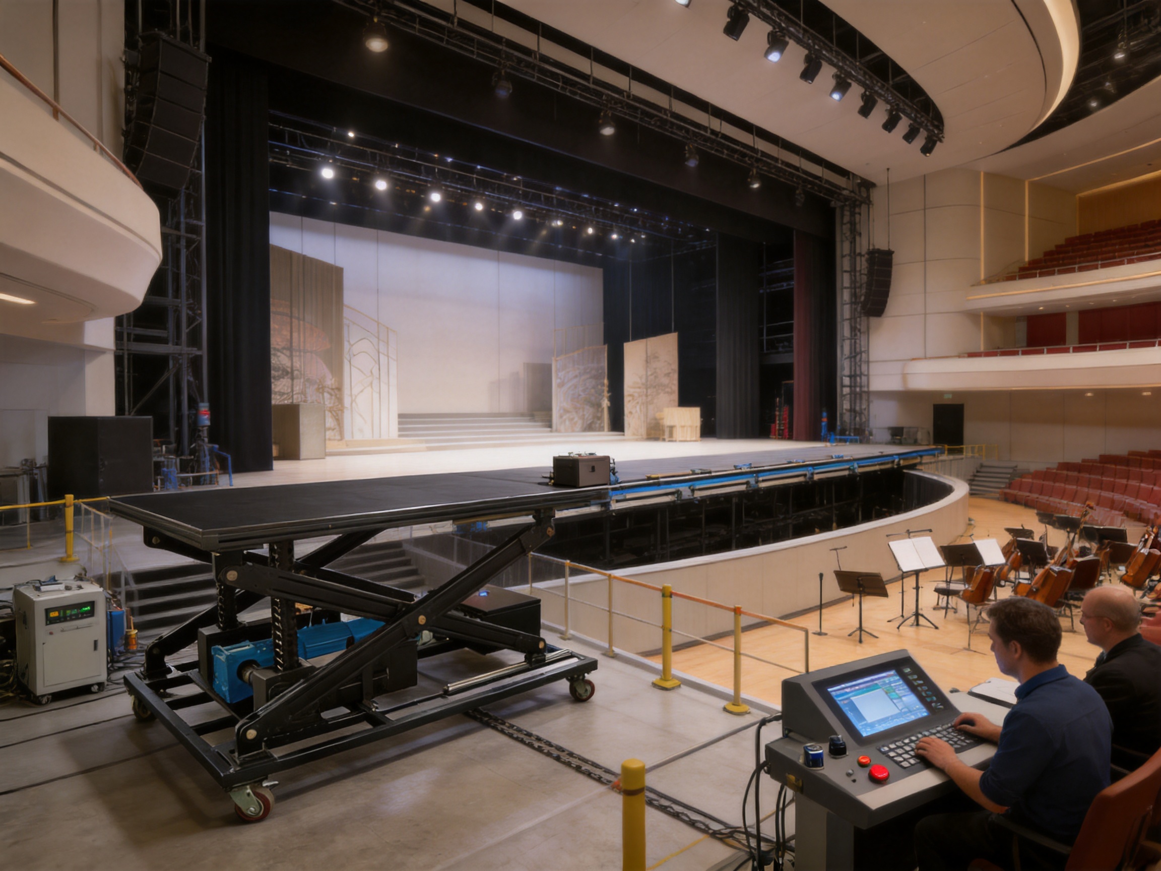
Modern performance venues require stage machinery that is accurate, quiet, dependable, and capable of repeated operation under demanding conditions. A lift table is not simply a platform with a motor underneath it. It is an integrated mechanical and control system that must move performers, scenery, instruments, vehicles, or architectural stage sections while maintaining stable alignment and predictable timing. The Rigid/Screw/Rack/Chain Lifting Chain Lift Table is designed to meet these requirements through a combination of rigid chain lifting technology, modular load distribution, linear guidance, X-tracing support, geared drive transmission, and digital control compatibility.
Developed for automation artistic stage machinery, this lift table provides a practical solution for stage-level changes, vertical platform movement, orchestra pit conversion, scenic lifting, access platforms, and other applications requiring controlled vertical travel. Its standard lifting velocity can reach up to 150 mm/s, while the mechanical arrangement is designed to maintain smooth movement and consistent force throughout the operating cycle.
The equipment is manufactured and supplied by RenteZhihe (JiangSu) Equipment Technology Co., Ltd., a high-tech enterprise specializing in stage machinery, performance equipment, and intelligent control systems. The company combines mechanical design, manufacturing, installation, commissioning, and maintenance capabilities to provide integrated solutions for theaters, cultural centers, stadiums, conference centers, and multifunctional performance spaces.
Stage lifting systems operate in an environment where movement quality is highly visible. In a general industrial lifting application, a small vibration or a minor variation in speed may be acceptable. On a performance stage, however, the same issue can interrupt choreography, affect scenic alignment, create unwanted noise, or reduce the confidence of performers stepping onto the platform.
A stage lift must therefore satisfy several requirements at the same time. It must provide sufficient load capacity, maintain a level platform, resist horizontal and twisting forces, operate at a controlled speed, fit within the architectural limits of the venue, and integrate with the wider stage automation system. It should also be serviceable, adaptable to different platform sizes, and reliable over many operating cycles.
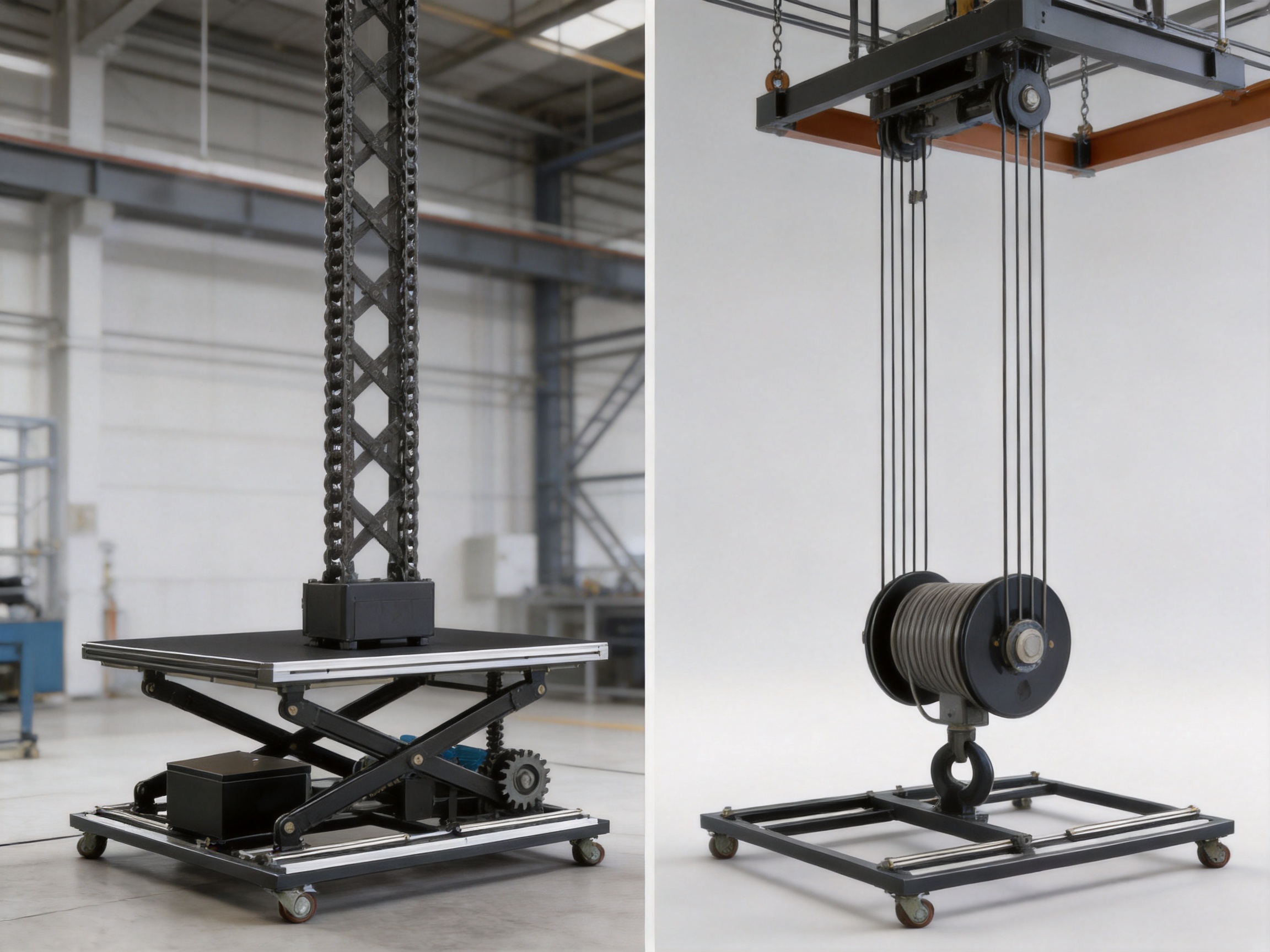
The Rigid/Screw/Rack/Chain Lifting Chain Lift Table addresses these requirements through a coordinated mechanical structure rather than depending on a single lifting component. The rigid chain supplies the vertical driving force. Linear guides control the direction of travel. X-tracing supports reinforce the platform against deformation and twisting. The motor and reducer provide controlled power transmission, while digital and inverter control systems regulate acceleration, stopping, positioning, and operating sequences.
This division of functions is important. The chain is responsible for lifting, but it is not expected to solve every structural problem by itself. The guide system manages the travel path, the support structure handles platform stability, and the control system manages the timing and precision of movement. This integrated approach gives the lift table a strong foundation for use in automated stage machinery.
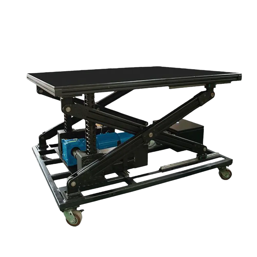
Rigid/Screw/Rack/Chain Lifting Chain Lift Table
A rigid chain lift uses interlocking chain links that can be stored compactly in a chain box when retracted and form a rigid, self-supporting column when extended. This operating principle allows the chain to transmit force vertically while occupying less space than a permanently extended support column.
Unlike a conventional wire-rope system that primarily lifts through tension, a rigid chain can push as well as pull. When the chain is extended, its interlocking links create a stable load-bearing structure. This makes it possible to drive a stage platform upward from below without relying entirely on an overhead suspension point.
The push-pull characteristic provides several practical advantages for stage construction. The equipment can be installed where overhead rigging space is limited or unavailable. It can also support lift-table arrangements in which the driving mechanism is positioned below or beside the platform. This flexibility is valuable in existing theaters, renovation projects, architectural platforms, and venues where the ceiling structure has already been allocated to lighting, scenery, curtains, speakers, or other systems.
When the chain is retracted, it is stored inside a dedicated chain box. Compact storage reduces the amount of vertical space required below the platform and helps protect the chain from unnecessary exposure. The exact arrangement can be adapted to the platform dimensions, travel requirements, and load distribution plan of the project.
The drive system normally consists of an electric motor, reducer, and chain-lifting assembly. The motor generates rotational power, the reducer converts that power into suitable torque and speed, and the lifting mechanism transfers the output to the rigid chain. Because the chain movement is directly associated with reducer output, the relationship between drive speed and lifting speed can be controlled in a predictable manner.
Wire-rope and cable systems remain useful in many forms of stage machinery, especially where long travel, overhead suspension, or flexible routing is required. However, a rigid chain lift table offers a different set of advantages when the application involves a compact vertical platform that must feel solid and remain accurately positioned under load.
The first advantage is structural stiffness. A cable supports a load through tension and may exhibit elastic stretch or small movement changes as the load varies. A rigid chain, once extended into its interlocking column, creates a more direct load path. This can help reduce the sense of platform “give” that may be noticed when performers or technicians step onto a lifted surface.
The second advantage is the ability to push as well as pull. A cable-based lift generally requires an upper anchoring point, a drum, a sheave system, or a counterweight arrangement. A rigid chain can be configured to push the platform upward from below, which may simplify the building interface and expand the available installation locations.
The third advantage is compact storage. The chain can be gathered into a chain box instead of remaining suspended in a long vertical line. This can help reduce the required machine-room height and provide greater freedom when planning the underside of a stage platform.
The fourth advantage is compatibility with modular configurations. A light platform may use a single chain. Larger or heavier platforms can use double chains or multiple synchronized chains. This allows the lifting arrangement to be selected according to the actual load and platform geometry rather than forcing every project into one fixed architecture.
The following comparison summarizes the principal differences between a rigid chain lift table and a typical cable-based vertical lift arrangement.
| Design consideration | Rigid chain lift table | Typical cable-based lift |
|---|---|---|
| Primary lifting action | Push-pull force through interlocking rigid links | Primarily tension through a flexible cable |
| Installation requirement | Can be arranged without a dedicated overhead suspension point | Often requires overhead anchoring, sheaves, or a supporting frame |
| Compact storage | Chain can be stored in a chain box | Cable normally winds onto a drum or passes through a routing system |
| Load distribution | Single, double, or multiple synchronized chains | Multiple cables, drums, or reeving arrangements may be required |
| Platform stability | Supported by rigid lifting elements, guides, and X-tracing | Usually depends more heavily on guide rails, suspension geometry, and cable tension |
| Control integration | Suitable for inverter and digitalized control systems | Also possible, but control behavior depends on cable elasticity and mechanical arrangement |
The choice between technologies should always be based on the application, load, travel, available space, maintenance plan, and venue requirements. The rigid chain lift table is especially suitable when compact construction, direct vertical support, modular load capacity, and stable stage-level positioning are high priorities.
One of the most useful features of this lift table is its modular chain configuration. Stage platforms vary substantially in size and payload. A small access platform, a scenic elevator, and a full orchestra pit platform do not impose the same mechanical demands. The ability to use one, two, or several synchronized chains makes the equipment adaptable to different project conditions.
A single-chain arrangement can be appropriate for a smaller platform or a lighter payload when the load is suitably centered and the structure is designed to resist rotation. It can provide a relatively simple mechanical layout and may reduce the amount of space required for the lifting assembly.
A double-chain arrangement can distribute the lifting force across two points. This is useful when the platform is wider, when the center of gravity varies during operation, or when a more balanced support arrangement is required. The two chains must be synchronized so that they extend and retract together while maintaining the platform in a level position.
Multiple-chain arrangements are intended for larger platforms, heavier payloads, or applications where the load needs to be distributed across several structural points. The additional chains can reduce the load carried by each individual lifting element and support a more even transfer of force into the platform frame.
Synchronization is essential in every multi-chain configuration. If one chain travels faster than another, the platform may tilt, bind against the guide system, or experience uneven structural loading. For this reason, chain configuration is not simply a matter of adding more lifting elements. The mechanical transmission, reducer arrangement, shafting, guide design, and control strategy must be coordinated from the beginning of the project.
RenteZhihe’s engineering approach treats chain count as part of the overall system design. Load, platform dimensions, travel distance, center of gravity, support locations, operating frequency, and venue architecture can all be considered when selecting the appropriate configuration. This provides a scalable route from smaller automated platforms to larger stage lifting assemblies.
The lifting chain supplies vertical force, but a stage platform also needs a controlled travel path. Linear guides are used to constrain the platform as it moves upward and downward. They help prevent lateral drift and support accurate positioning throughout the stroke.
Guides are particularly important when the platform is subject to uneven or off-center loads. A performer, piece of scenery, instrument, or vehicle may not always be positioned exactly at the geometric center. Without suitable guidance, an offset load can create lateral forces that cause the platform to move away from its intended path.
X-tracing supports provide an additional structural function. The diagonal bracing arrangement increases resistance to twisting and helps the platform retain its geometry under uneven loading. It also supports the relationship between the platform frame and the vertical lifting elements.
The combination of rigid chain, linear guides, and X-tracing creates a layered stability system. Each component addresses a different operating challenge:
| Component | Primary function | Operational benefit |
|---|---|---|
| Rigid chain | Generates vertical push-pull lifting force | Direct, compact, and structurally supported elevation |
| Chain box | Stores retracted chain links | Space-efficient arrangement below or beside the platform |
| Linear guides | Control the platform travel path | Reduced lateral movement and improved positional accuracy |
| X-tracing supports | Resist twisting and diagonal deformation | Improved stability during uneven or off-center loading |
| Motor and reducer | Supply and regulate mechanical power | Controlled speed, torque, and repeatable movement |
| Digital or inverter control | Manage operation, speed, and positioning | Integration with automated stage sequences and safety logic |
This coordinated design is more effective than treating the chain as an isolated lifting component. Long-term accuracy depends on the complete structural and mechanical arrangement, including the stiffness of the platform, the alignment of guides, the synchronization of chains, and the quality of the control system.
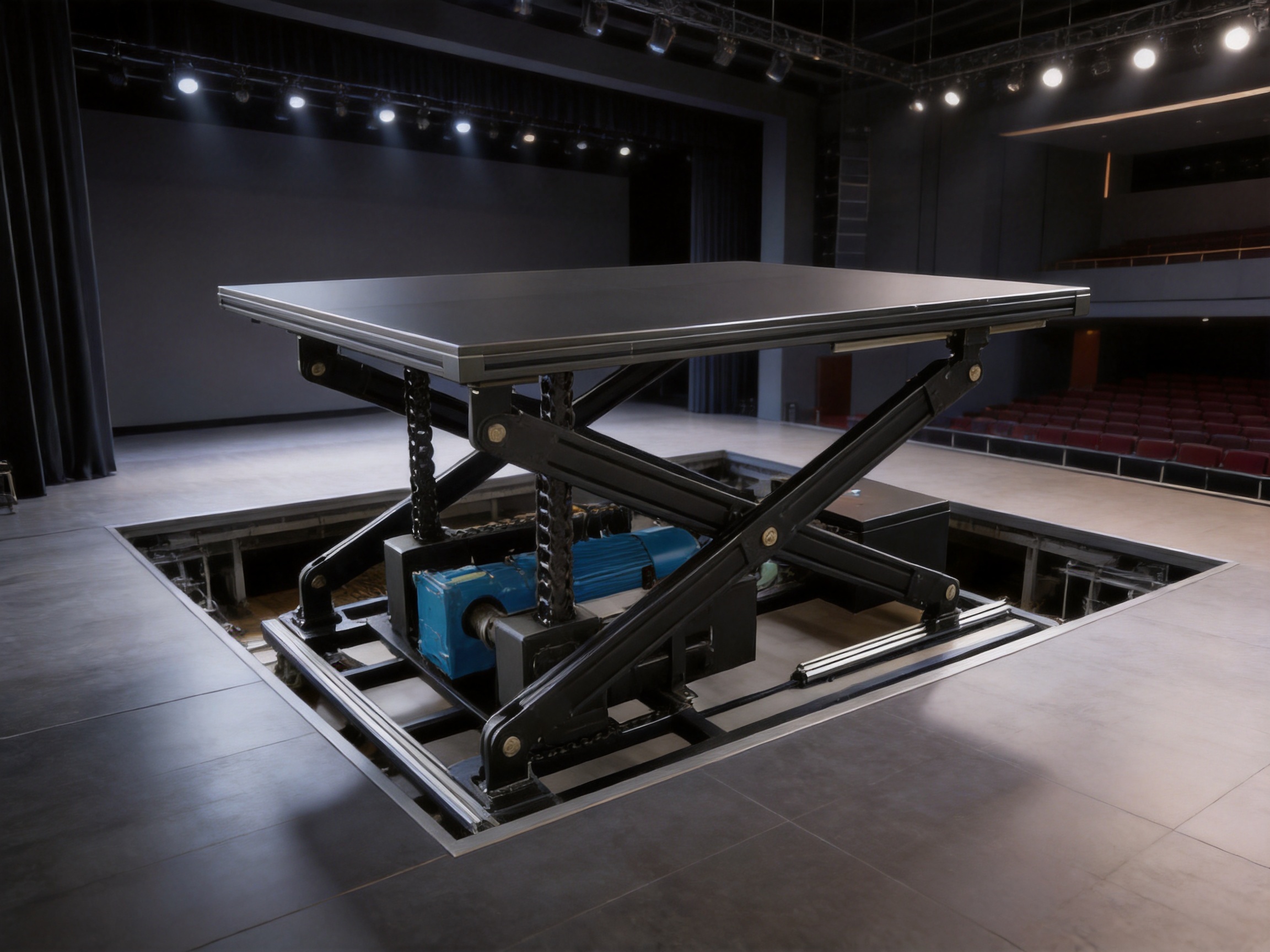
The standard lifting velocity of up to 150 mm/s provides a useful balance between stage responsiveness and controlled movement. For a live performance, the significance of this rating is not only the maximum speed. The more important question is whether the lift can achieve that speed smoothly, maintain a predictable output, and stop accurately at the intended position.
Stage automation often operates according to programmed cues. A platform may need to rise during a musical transition, align with a scenic reveal, meet an orchestra-level configuration, or return to the stage surface before the next performance sequence. If the movement time changes from cycle to cycle, the lift can disrupt the timing of lighting, sound, video projection, or performer movement.
A reducer-based drive provides a direct relationship between motor output, reducer speed, chain movement, and platform travel. When combined with inverter control, the system can manage acceleration and deceleration rather than simply switching the motor on and off. This supports smoother starts, controlled stops, and reduced mechanical shock.
Speed selection should be based on the complete application. A short-travel platform may not need the maximum rated velocity. A larger platform carrying a sensitive scenic element may require a slower programmed profile for comfort and stability. Digitalized control allows the operating speed to be selected according to the cue, load condition, and venue requirements.
The specified velocity should also be considered alongside travel distance. At 150 mm/s, a 1,500 mm vertical stroke would require approximately ten seconds at constant speed, excluding acceleration and deceleration. Actual cycle time depends on the programmed motion profile, mechanical configuration, load, and control settings. This provides designers with a practical basis for coordinating the lift table with other stage systems.
Modern theaters increasingly rely on centralized automation. Stage lifts may operate together with lighting, projection, sound, curtain systems, turntables, movable scenery, and safety monitoring equipment. A lift table must therefore be capable of receiving controlled commands and returning useful operating information to the wider system.
The product is compatible with digitalized control systems and inverter control. Inverter technology allows the motor speed to be regulated and supports controlled starting and stopping. Digital control can also be used to define operating positions, travel limits, speed profiles, and coordinated cues, subject to the project’s selected control architecture.
Precise control is particularly valuable for repeatable positioning. A platform can be programmed to stop at stage level, a partial-rise position, an orchestra-level position, or a maintenance position. Multiple target positions can support different venue configurations without requiring manual mechanical adjustment for every change.
Control integration must be designed together with mechanical safety. Software commands should not be treated as a substitute for physical protection, guide alignment, load assessment, or emergency stopping arrangements. The most dependable systems combine mechanical limits, electrical interlocks, monitored operating states, and appropriate control logic.
Because the lift table is intended for professional stage environments, the control system should also support clear operating procedures. Operators need to understand the platform’s permitted load, travel range, access conditions, emergency response, and maintenance status. Well-organized control architecture helps turn the mechanical lift into a dependable part of the venue’s production workflow.
Safety is a central consideration in any platform lifting application. The rigid chain system is designed to bear both vertical and horizontal loads, while the platform structure, guides, and X-tracing supports work together to control movement. The chain’s compact storage inside a chain box also helps organize the mechanism and protect the retracted links.
Mechanical stability is supported by the chain configuration and guide structure. When multiple chains are used, synchronization helps keep the platform level and reduces the possibility of uneven loading. The use of an appropriate reducer and controlled drive output helps prevent abrupt movement during normal operation.
Safety functions should be selected according to the specific venue and application. Depending on the design, these may include travel limit devices, emergency stop circuits, access interlocks, overload monitoring, position feedback, mechanical stops, inspection access, and control-system fault handling. The final safety design must be confirmed during engineering, installation, commissioning, and acceptance testing.
Quiet operation is another important aspect of safety and user confidence. Excessive noise can interfere with performances and may indicate vibration, misalignment, or mechanical impact. The lift table is designed for quiet and reliable operation through controlled transmission, stable guiding, and a properly assembled support structure. Regular inspection and lubrication, where specified, are necessary to maintain these characteristics over the service life.
Safe operation also depends on human factors. Operators should receive clear instructions for normal use, emergency stopping, inspection, maintenance coordination, and load control. The venue should establish procedures that prevent people from entering a hazardous movement area while the platform is in operation. A well-designed product performs best when supported by disciplined operational management.
The quality of a stage lift table depends not only on its design concept but also on how accurately that concept is converted into a finished assembly. RenteZhihe combines product research and development with manufacturing, installation, commissioning, operation support, and maintenance services. This integrated capability helps connect engineering decisions with real installation conditions.
The manufacturing process begins with application analysis. Engineers review the required travel, platform dimensions, estimated loads, load distribution, duty cycle, installation environment, control requirements, and available machine space. This stage is essential because the correct number of chains, guide arrangement, motor and reducer selection, and structural dimensions depend on the complete application rather than on a single specification.
After the basic configuration is established, the mechanical structure can be developed around the chain-lifting assembly. The platform frame, guide supports, X-tracing members, chain boxes, motor base, reducer position, and maintenance access points must be arranged as one coordinated system. This reduces the risk of interference between components and makes installation more straightforward.
Fabrication accuracy is particularly important in the guide and chain alignment. If the lifting elements are not aligned with the platform structure, the system may experience uneven loading or unnecessary friction. Manufacturing and assembly procedures should therefore pay close attention to frame squareness, connection accuracy, shaft alignment, guide positioning, and the relationship between the reducer output and the chain drive.
Mechanical components can be prepared through a combination of structural fabrication, precision machining, component fitting, and controlled assembly. The exact process depends on the project design, but the objective remains consistent: to produce a rigid, accurately aligned, serviceable lifting mechanism that performs consistently after installation.
Quality control should be considered at several stages rather than only at final delivery. Incoming components need to match the design requirements. Fabricated frames should be checked for dimensional accuracy. Moving parts should be inspected for smooth operation. Electrical and control components should be verified for compatibility. Final assemblies should be tested for travel, position, speed, synchronization, noise, and response to control commands.
Factory preparation also provides an opportunity to identify issues before the equipment reaches the venue. Where practical, assemblies can be checked for fit, access, cable routing, chain storage, maintenance clearances, and connection interfaces. This can reduce installation adjustments and support a more efficient commissioning process on site.
The following priorities are particularly important when manufacturing a rigid chain lift table:
Structural integrity: The platform frame and support members must be designed and fabricated to handle the intended vertical and horizontal forces without unacceptable deformation.
Alignment accuracy: Chain drives, guides, shafts, and platform connections must work along the intended axes to avoid binding and uneven load distribution.
Component compatibility: The motor, reducer, chain assembly, guide system, control equipment, and structural frame must be selected as a complete system.
Serviceability: Inspection points, lubrication areas, chain boxes, electrical interfaces, and access panels should be arranged so that maintenance can be performed efficiently.
Control readiness: The mechanical system should be prepared for inverter control, digital commands, position monitoring, and safety interlocks as defined by the project.
Testing discipline: The completed lift should undergo functional testing before being released for installation or venue operation.
Installation begins with a review of the venue conditions. The foundation, pit, supporting structure, platform opening, available clearance, electrical supply, control-room interfaces, and access route must be confirmed before equipment is positioned. A lift table can be well manufactured and still perform poorly if the supporting structure is not prepared accurately.
The platform and lifting assembly must be installed in accordance with the approved mechanical arrangement. Linear guides need to be positioned so that the platform can travel without excessive resistance. Chain boxes should remain accessible for inspection, and the motor and reducer should have adequate ventilation and maintenance space.
After mechanical installation, the system is commissioned in stages. Initial checks normally include fastener inspection, alignment verification, chain movement, guide clearance, reducer operation, lubrication status, electrical connections, control signals, and travel limits. The platform can then be operated at low speed before progressive testing through the complete travel range.
Multi-chain systems require special attention during commissioning. Each chain must extend and retract in synchronization, and the platform must remain level throughout the travel. Any unusual sound, vibration, resistance, or uneven movement should be investigated before the lift is placed into normal service.
Control integration follows mechanical verification. The lift can be connected to the venue’s digital stage management system, inverter panel, or local control station according to the project design. Operators should confirm command response, stop functions, position feedback, limit behavior, emergency procedures, and communication with other automated equipment.
Commissioning should include operational scenarios that reflect actual use. These may include empty travel, rated-load testing, repeated cycles, intermediate stops, stage-level positioning, emergency stopping, and coordinated cues. The exact test program depends on the venue’s technical requirements and applicable safety procedures.
The lift table can be adapted to a range of stage and architectural applications. Its compact chain storage and modular configuration are useful when a venue needs vertical movement but has limited space for conventional lifting equipment.
Orchestra pit lifts are one possible application. A platform can move between stage level, orchestra level, and storage or maintenance positions. Smooth positioning is important because musicians, instruments, music stands, and associated equipment may be present on the platform.
Scenic lifts can raise or lower set pieces, vehicles, decorative structures, and production elements. The rigid chain’s push-pull capability can support platforms that need to emerge through the stage rather than descend from an overhead system.
Performer lifts can provide controlled entrances and exits. In these applications, low vibration, predictable timing, and accurate stopping are especially valuable. The platform should transition naturally with the surrounding stage surface when it reaches its target position.
Stage extensions and movable floor sections can use lifting tables to change the architectural configuration of a venue. A platform may be raised for a performance, lowered to create additional seating or orchestra space, or positioned at an intermediate height for a special event.
Conference centers and multifunctional halls may also use automated platforms to reconfigure spaces. The lift table can become part of a broader system that supports concerts, presentations, ceremonies, exhibitions, and theatrical performances.
In each application, the final design should be based on the actual payload, platform size, operating frequency, travel distance, control requirements, and safety conditions. The modular nature of the product provides flexibility, but professional engineering remains essential.
Stage machinery often operates for many years and may be used intensively during production periods. Long-term performance depends on planned maintenance as much as on initial manufacturing quality.
Routine inspection should cover the rigid chains, chain boxes, guide components, X-tracing supports, platform frame, motor, reducer, fasteners, electrical connections, sensors, and control cabinets. Inspection intervals should be established according to operating frequency, environmental conditions, manufacturer recommendations, and venue procedures.
The chains should be checked for abnormal wear, damage, contamination, deformation, and unusual movement. The chain storage area should remain clean and free from objects that could interfere with retraction. Guide components should be inspected for alignment, wear, and smooth travel. X-tracing supports and structural connections should be checked for looseness or damage.
The motor and reducer should be monitored for unusual temperature, noise, vibration, leakage, or changes in operating behavior. Any change in speed or stopping accuracy may indicate a control issue, mechanical wear, alignment problem, or lubrication requirement.
Maintenance records should document inspections, adjustments, repairs, replacement parts, control changes, and operational tests. Good records help venue managers identify trends before a small issue becomes a production interruption.
RenteZhihe’s service system covers design, production, installation, commissioning, operation, and maintenance. This full-cycle capability is valuable because stage machinery performance depends on continuity between these phases. The people who understand the design intent can help interpret installation conditions, commissioning results, and future service requirements.
Purchasing a lift table from an integrated stage machinery manufacturer provides advantages beyond the physical product. Mechanical lifting, structural engineering, controls, installation, and maintenance are closely connected. If these areas are handled by separate parties without effective coordination, responsibility for performance can become unclear.
An integrated manufacturer can review the complete application and recommend a suitable configuration. It can coordinate chain count, guide placement, platform structure, motor and reducer selection, control interfaces, and installation requirements. This reduces the risk of specifying isolated components that do not work efficiently together.
RenteZhihe focuses on stage machinery, performance equipment, and intelligent control systems. Its products are intended for professional venues where safety, repeatability, and service support are important. The company’s experience across theaters, cultural centers, stadiums, conference centers, and multifunctional performance spaces gives it an understanding of the different architectural and operational environments in which stage equipment must function.
The company also emphasizes cooperation throughout the project lifecycle. Design support is followed by production, installation, commissioning, operation assistance, and maintenance. This approach enables customers to obtain more than a standard mechanical product. They receive a stage automation solution developed around the conditions of the venue.
For international customers, direct communication with the manufacturer can also simplify technical clarification. Questions regarding platform dimensions, chain configuration, control interfaces, installation access, spare parts, and maintenance can be addressed through one engineering relationship.
Before specifying a rigid chain lift table, project teams should collect the following information:
Platform dimensions and shape.
Maximum live load, dead load, and estimated center of gravity.
Required lifting travel and available installation depth.
Target operating speed and acceptable acceleration or deceleration.
Expected operating frequency and duty cycle.
Whether the platform will carry people, scenery, instruments, vehicles, or mixed loads.
Required number of intermediate positions.
Available electrical supply and control-system architecture.
Required safety devices, emergency controls, and access interlocks.
Environmental conditions, including dust, moisture, temperature, and proximity to public areas.
Maintenance access, inspection routes, and spare-parts requirements.
Installation schedule and available lifting or handling equipment.
This information enables the manufacturer to determine whether a single-chain, double-chain, or multiple-chain configuration is appropriate. It also supports correct selection of the guide system, platform reinforcement, drive assembly, and control arrangement.
A rigid chain lift table is a vertical platform system that uses interlocking chain links to generate lifting force. When extended, the chain forms a rigid supporting column. When retracted, it can be stored in a compact chain box. The complete system also includes a motor, reducer, guides, platform structure, supports, and control equipment.
A rigid chain can push as well as pull, while a cable primarily lifts through tension. This allows a rigid chain lift to operate without depending entirely on an overhead suspension point. The rigid chain also provides a direct support path and can be stored compactly when retracted.
Yes, the system can be configured with a single chain, double chains, or multiple synchronized chains according to the platform size, payload, and load distribution. The appropriate configuration must be determined through project-specific mechanical engineering.
Synchronization keeps every chain moving at the same rate. Without synchronization, one side of the platform could rise faster than another, causing tilting, uneven loading, guide resistance, or mechanical damage.
Linear guides constrain the platform’s travel path and help prevent lateral drift. They are especially important when the platform experiences off-center loads or when accurate positioning is required.
X-tracing supports reinforce the platform structure and resist twisting or diagonal deformation. They complement the lifting chains and guides by improving stability when loads are uneven or distributed away from the center.
A maximum standard lifting velocity of up to 150 mm/s is suitable for many stage-level movements. The actual programmed speed should be selected according to the travel distance, load, performance cue, platform use, and required acceleration and stopping behavior.
Yes. The lift table is compatible with digitalized control systems and inverter control. Integration can include speed regulation, programmed positions, coordinated cues, limit monitoring, and emergency control functions according to the project architecture.
The rigid chain’s push-pull operating principle means that the lift can be designed without relying on a conventional overhead cable suspension point. The final installation still requires suitable structural support, guides, clearances, and foundations.
Retracted chain links are designed to be stored in a chain box. This arrangement helps keep the lifting mechanism compact and organized within the available machine space.
Commissioning should verify mechanical alignment, chain synchronization, smooth travel, speed, stopping accuracy, platform level, guide operation, limit devices, emergency stops, control commands, noise, vibration, and performance under appropriate load conditions.
Maintenance includes inspection of chains, chain boxes, guides, X-tracing supports, platform connections, motor, reducer, fasteners, sensors, cables, and control equipment. Lubrication, adjustment, cleaning, and replacement of worn components should follow the manufacturer’s procedures and the venue’s maintenance schedule.
The modular chain arrangement and integrated engineering approach allow the lift table to be developed around project requirements such as platform dimensions, load, travel, speed, control interface, and installation environment. Customization should be reviewed with the manufacturer before production.
The Rigid/Screw/Rack/Chain Lifting Chain Lift Table provides a practical and adaptable approach to automated vertical stage movement. Its rigid chain mechanism offers push-pull lifting capability, compact storage, and a direct structural load path. Modular single, double, and multiple-chain configurations allow the system to be scaled according to platform size and payload.
Its performance is strengthened by the combination of linear guides, X-tracing supports, motor and reducer transmission, and digital control compatibility. These elements work together to provide stable movement, accurate positioning, smooth operation, and repeatable timing. The standard lifting velocity of up to 150 mm/s supports responsive stage changes while allowing the control system to manage acceleration, deceleration, and stopping.
The product’s value also depends on the manufacturing and service capabilities behind it. RenteZhihe integrates research and development, fabrication, assembly, installation, commissioning, operation support, and maintenance. This complete process helps ensure that the lift table is considered not as an isolated mechanism but as part of the venue’s full stage automation system.
For theaters, cultural centers, stadiums, conference venues, and multifunctional performance spaces, a rigid chain lift table can provide a reliable foundation for stage-level transformation. When correctly engineered, installed, operated, and maintained, it supports the safety, precision, and creative flexibility required by modern performance environments.
1. RenteZhihe (JiangSu) Equipment Technology Co., Ltd., Product Information for Rigid/Screw/Rack/Chain Lifting Chain Lift Table.
2. RenteZhihe (JiangSu) Equipment Technology Co., Ltd., Company Information and Stage Machinery Service Overview.
3. Stage machinery design principles concerning vertical lifting platforms, mechanical guidance, load distribution, and control integration.
4. General engineering practices for motor-reducer transmission systems, rigid chain mechanisms, linear guide assemblies, and structural bracing.
5. General technical practices for theater automation, stage lift commissioning, operational safety, and preventive maintenance.
We specialize in delivering advanced stage machinery, rigging systems and intelligent control solutions for performance spaces worldwide.

No. 111 Runfeng Road, Hailing District, Taizhou City, Jiangsu Province, China

rtstage@163.com

+86-139 1771 1698

+86-139 1771 1698
rtstage@163.com
 中文简体
 English
 русский
 Français
 Español
 عربى