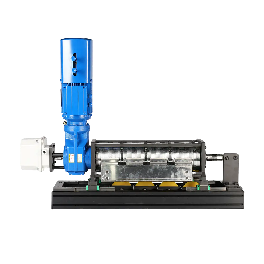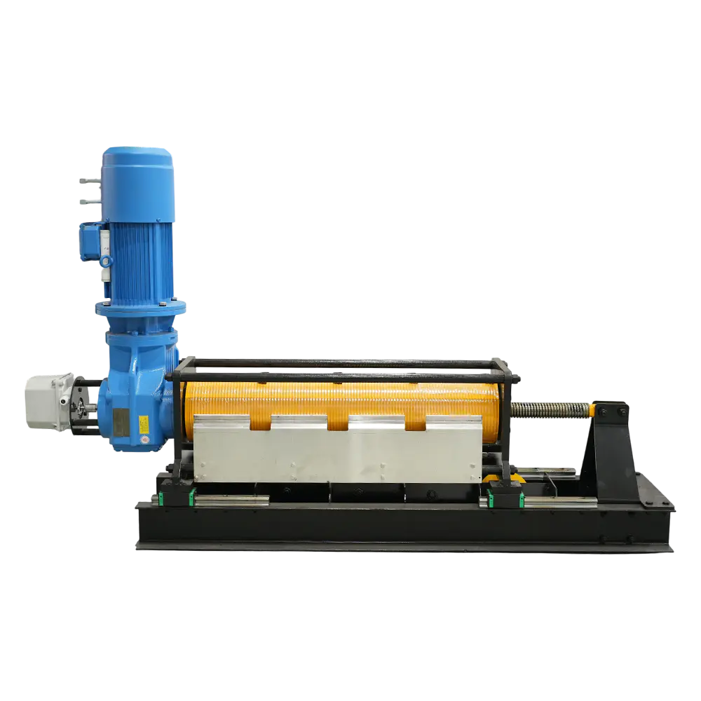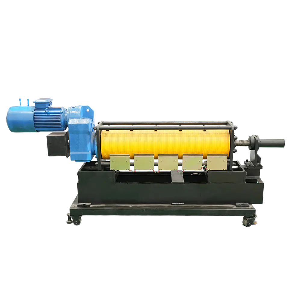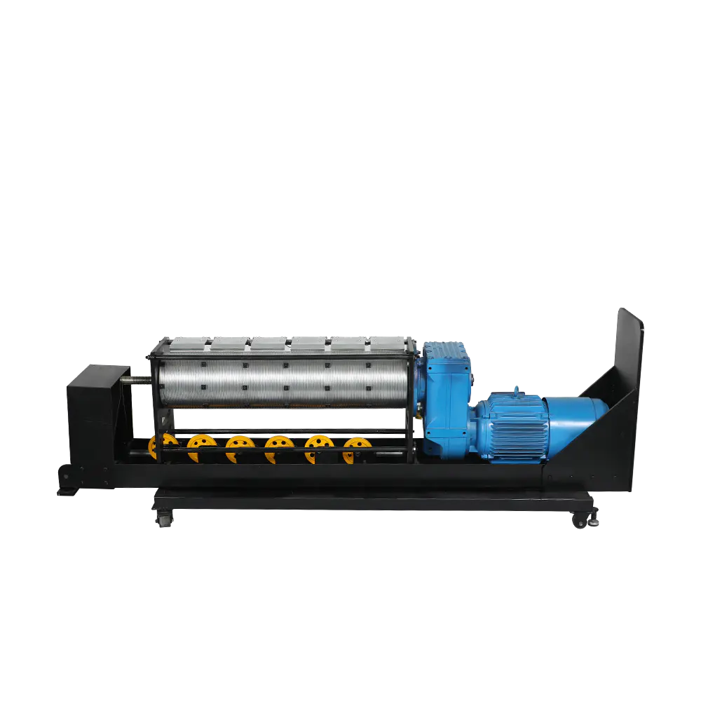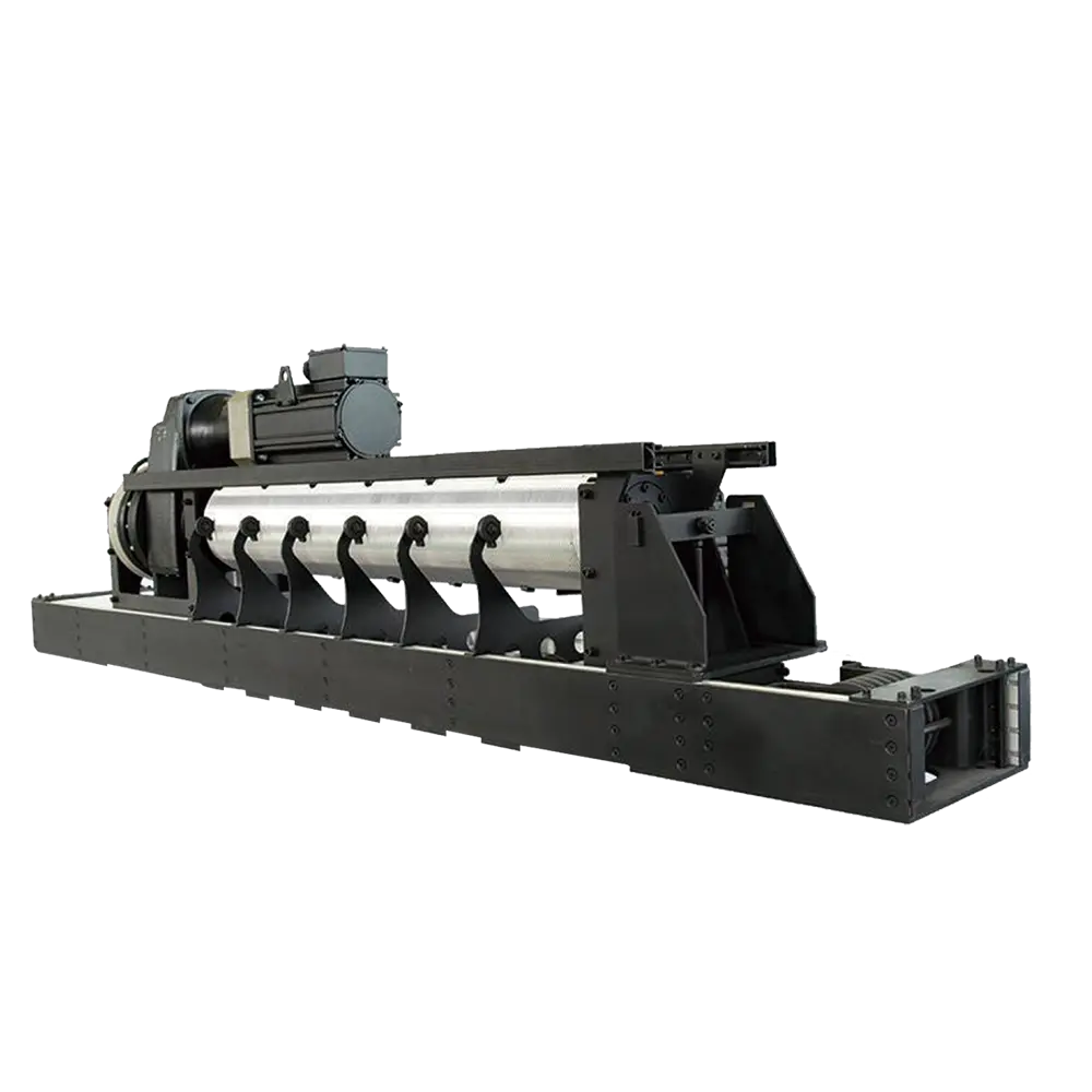
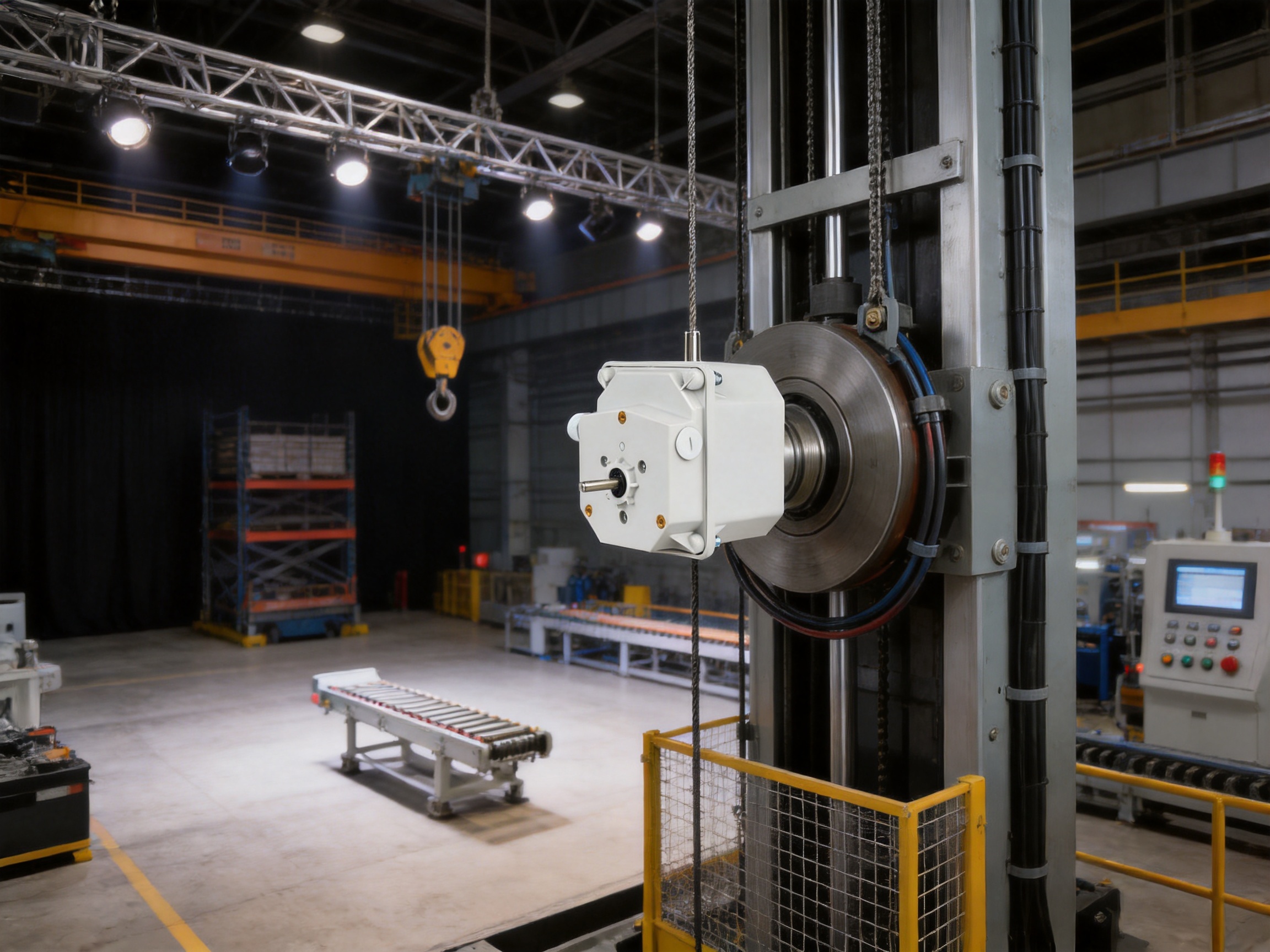
Modern stage machinery depends on accurate movement, repeatable positioning, and dependable safety protection. Stage winches, pile winders, hoists, lifts, lighting trusses, battens, fire curtains, and other automated systems must move along carefully defined travel paths. When a moving assembly exceeds its permitted position, the result can include equipment damage, production delays, expensive repairs, or serious safety incidents. A reliable position-control device is therefore not an optional accessory. It is a fundamental part of the mechanical and electrical safety architecture.
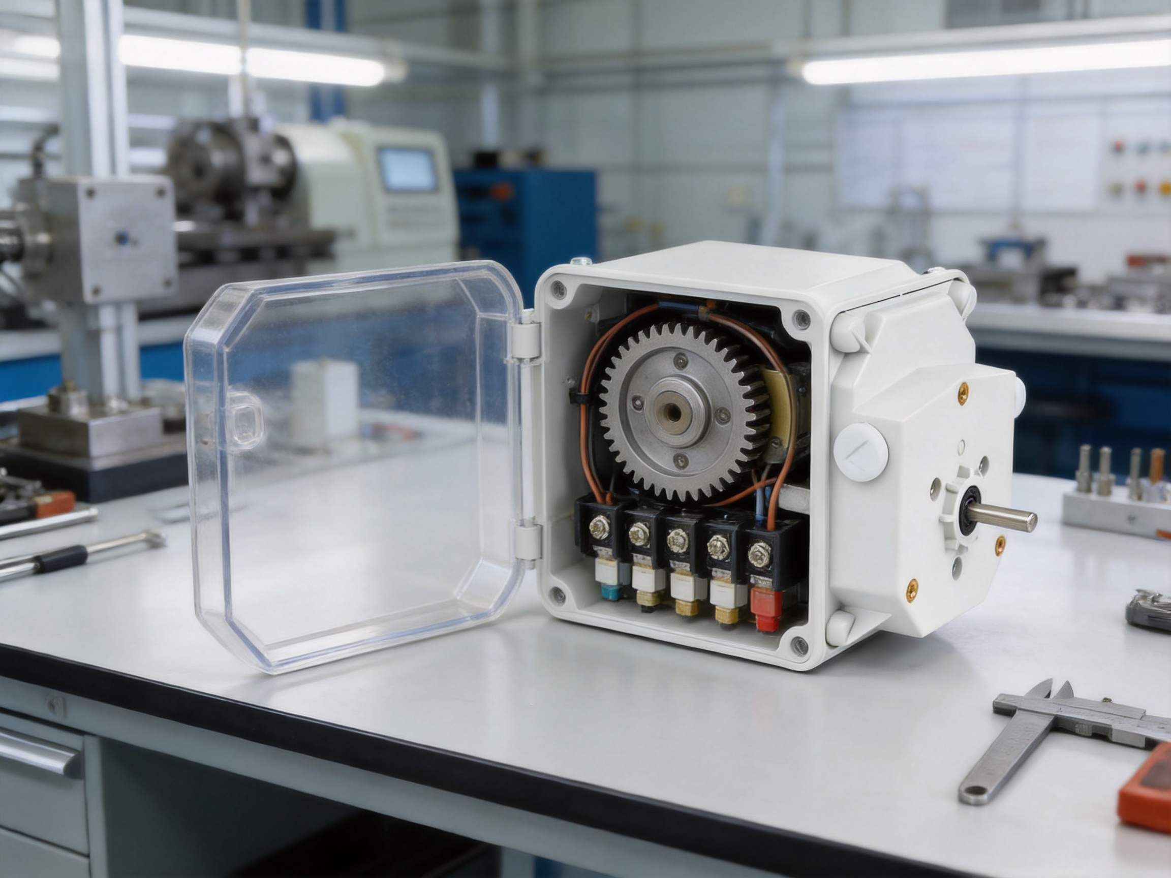
The Gear Limit Switch is designed to meet this requirement. By combining a precision gear transmission system, a self-locking worm, adjustable cam discs, and independent microswitches, it converts shaft rotation into dependable travel-limit signals. The device can monitor the movement of stage winches and other machinery, trigger stopping or control functions at preset positions, and provide repeatable protection throughout extended operating cycles.
Compared with basic direct-contact limit switches, a gear limit switch is better suited to equipment that travels over long distances or requires position detection based on multiple shaft rotations. Its mechanical reduction system provides a controlled relationship between the driven shaft and the internal cam mechanism. This makes it possible to set several independent operating points for functions such as slow-down, stop, reverse, alarm, and emergency protection.
For demanding stage applications, performance depends on more than the switch itself. The quality of the gears, the accuracy of cam adjustment, the strength of the housing, the reliability of the microswitches, and the consistency of manufacturing all influence the final result. A professional manufacturer must therefore combine mechanical design expertise, precision processing, systematic assembly, functional testing, and engineering support. This article explains how a high-performance Gear Limit Switch works, why it offers advantages over conventional alternatives, and how advanced manufacturing capabilities contribute to long-term reliability.
Gear Limit Switch
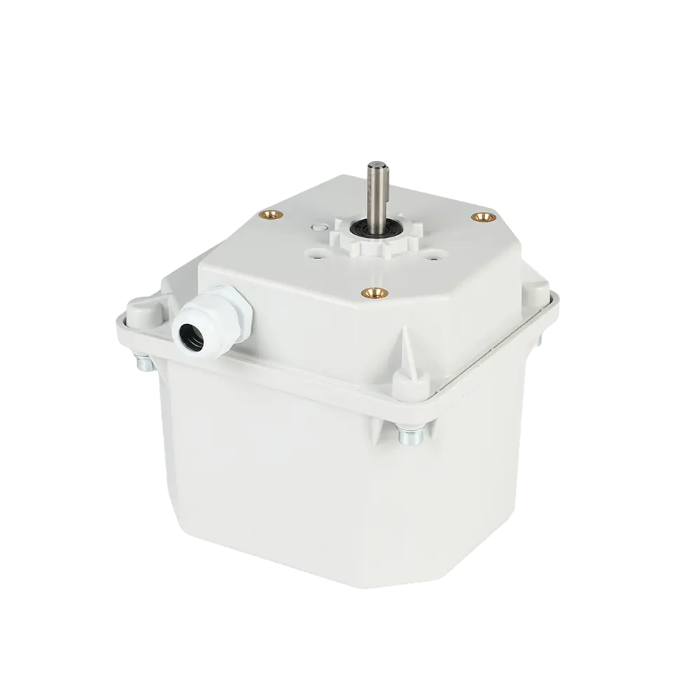
A Gear Limit Switch, also called a Rotary Limit Switch, is an electromechanical control device that detects the rotational position of a shaft and converts that position into one or more electrical signals. The device is normally connected to the rotating output of a winch, hoist, lift, or other motion system. As the equipment moves, its shaft rotates. The switch reduces and transfers this rotation through an internal gear train until adjustable cams reach their programmed actuation positions.
When a cam reaches a preset location, it operates a microswitch. The microswitch can open or close a control circuit depending on the required control logic. The resulting signal may stop a motor, engage a brake, activate a slow-speed command, initiate a reverse movement, trigger an alarm, or send status information to a control panel or programmable logic controller.
This design is particularly useful when the equipment has a long travel range. A simple mechanical limit switch may only detect a local physical contact. It does not normally track the accumulated rotation of a drum or shaft. A Gear Limit Switch, by contrast, uses the relationship between shaft rotation and internal gear movement to identify several specific positions during a complete operating cycle.
In stage machinery, this capability is important because one movement may require several control points. For example, a stage winch may need a slow-down point before reaching the upper limit, a normal stop point at the operating position, and a secondary safety point beyond the normal stop. A single enclosure with multiple independently adjustable microswitches can manage these functions in a coordinated way.
Stage equipment often operates above performers, technicians, scenery, lighting fixtures, and audiences. Many systems also work in confined spaces where a small positioning error can cause interference with adjacent equipment. The operational environment may change quickly, and equipment may be used repeatedly during rehearsals, performances, maintenance, and emergency procedures.
A stage winch must control the movement of wire ropes, drums, battens, curtains, or suspended loads. If the drum continues rotating after the load reaches its safe travel boundary, the wire rope may become over-wound, slack, damaged, or improperly aligned. If an upper limit is missed, a suspended assembly may collide with the structure above it. If a lower limit is exceeded, the equipment may strike the stage floor or another obstruction.
These risks are not limited to theaters. Similar challenges occur in concert halls, cultural centers, conference venues, stadiums, exhibition spaces, automated warehouses, lifting equipment, conveyors, elevator systems, and industrial production lines. Wherever a mechanical system must move to defined positions, travel limitation and position feedback are essential.
Electronic control systems and software-based monitoring provide valuable information, but they should not be the only protection layer. Mechanical position control offers an independent safeguard. Even if a sensor, communication module, or software routine fails, a properly adjusted mechanical limit switch can interrupt the drive circuit when the equipment reaches an unsafe boundary.
The operating principle is based on the controlled transfer of rotary motion. The equipment shaft is connected to the switch input or output shaft through a suitable coupling or mechanical interface. During operation, the shaft drives a planetary gear transmission system. The gear train reduces the input rotation and transfers it to the cam mechanism.
The reduction ratio determines how much equipment shaft rotation corresponds to one rotation of the internal cam assembly. By selecting an appropriate ratio, the switch can accommodate different travel distances, drum diameters, lifting heights, and operating cycles. The internal cam discs can then be adjusted to define the exact positions at which the microswitches are actuated.
The self-locking worm mechanism helps prevent unintended movement of the adjustment system. This is particularly important when the equipment experiences vibration, repeated acceleration and deceleration, or changes in load. Once the cam positions have been set, the worm and worm-wheel arrangement helps maintain the adjustment relationship during normal operation.
At a preset position, the profile of a cam contacts the actuator of a microswitch. Depending on the electrical configuration, the microswitch may open a normally closed circuit or close a normally open circuit. Multiple microswitches can be arranged to provide independent signals. The system can therefore create a sequence of control points rather than a single final stop.
The device operates at driving speeds of up to approximately 8.5 revolutions per minute while maintaining high repeatability. Its ability to provide consistent actuation at relatively high shaft speeds is a major advantage for automated stage systems that require both rapid movement and reliable stopping accuracy.
Every component in a Gear Limit Switch contributes to the stability of the complete control system. The following table summarizes the main elements and their roles.
| Component | Primary Function | Contribution to Performance |
|---|---|---|
| Protective housing | Encloses and protects internal parts | Improves resistance to dust, impact, vibration, and environmental exposure |
| Planetary gear set | Transfers and reduces shaft rotation | Provides compact, stable, and repeatable motion transmission |
| Self-locking worm | Drives and stabilizes the cam assembly | Helps prevent unwanted adjustment movement during operation |
| Worm-wheel cam structure | Converts reduced rotation into switching positions | Allows precise and convenient on-site adjustment |
| Cam discs | Define actuation points | Support multiple independent limit settings |
| Microswitch assembly | Outputs electrical control signals | Enables stopping, reversing, alarm, and sequencing functions |
| Output shaft | Connects the switch to the driven equipment | Provides direct mechanical feedback from the moving system |
| Electrical terminals | Connect internal switches to external circuits | Support secure and organized wiring |
The protective housing is commonly made from a flame-retardant material. This construction helps reduce the risk associated with heat and electrical faults while protecting the internal mechanism from accidental contact. The housing also supports the mounting structure and provides a stable reference for the internal components.
The planetary gear set is central to the product’s compact design. Planetary transmission distributes load through multiple gears and can achieve a useful reduction ratio without requiring a large enclosure. This design contributes to smooth operation, high carrying capacity, and consistent motion transfer.
The worm-wheel cam structure provides an important practical advantage. Instead of requiring complex disassembly or difficult recalibration, technicians can adjust the cam positions directly during commissioning or maintenance. The independent multiple-block design allows each microswitch to be configured according to its own function.
A direct-contact switch is generally suitable for detecting whether a moving part has reached a nearby physical point. It is less suitable for tracking long travel ranges or multiple turns of a shaft. A Gear Limit Switch uses controlled mechanical reduction to convert shaft rotation into stable cam movement. This arrangement supports accurate and repeatable switching positions over many operating cycles.
High repeatability is especially valuable in stage machinery. A batten or lift may be moved to the same position hundreds of times during rehearsals and performances. If the stop point changes gradually, the equipment may become misaligned with scenery, lighting, curtains, or other technical installations. Consistent switching helps maintain predictable operation.
Many conventional switches provide only one actuation point. The Gear Limit Switch can include multiple microswitches and independently adjustable cam blocks. This allows one device to manage several stages of motion control.
A typical configuration may include an approach or slow-down point, a normal stop point, a confirmation point, and an additional safety limit. Each setting can be adjusted to meet the equipment’s travel characteristics. This reduces the need for several separate devices and can simplify wiring, commissioning, and maintenance.
Stage machinery frequently requires adjustment after installation. Actual cable stretch, drum dimensions, load behavior, structural tolerances, and installation conditions may differ slightly from the original design assumptions. A switch that is difficult to adjust can increase commissioning time and maintenance costs.
The worm-wheel cam structure makes on-site adjustment more convenient. Technicians can calibrate the opening and closing positions of each microswitch according to the actual movement of the equipment. The independent adjustment structure also helps maintain the relationship between separate control points.
Space is often limited inside stage machinery galleries, hoist rooms, trusses, lifting frames, and control cabinets. A bulky position-control system may complicate installation or require additional support brackets. The compact design of the Gear Limit Switch helps integrate it into equipment with limited mounting space.
Its relatively light weight can also reduce the load placed on mounting structures. At the same time, the internal planetary transmission provides strong mechanical performance in a compact arrangement.
Stable gear engagement, controlled cam movement, and durable microswitches help the device operate smoothly. Smooth operation reduces unnecessary vibration and mechanical shock, which can benefit both the switch and the equipment connected to it.
Long service life depends on correct selection, installation, adjustment, and maintenance. When these conditions are met, the device can support continuous operation in demanding automation environments. Its mature mechanical design is suitable for systems that must operate reliably over extended periods.
The transmission system is designed to handle the mechanical forces associated with shaft rotation and repeated actuation. The planetary structure distributes the load, while the worm mechanism maintains stable cam movement. This provides a robust solution for winches, lifts, hoists, and other equipment that cannot tolerate inconsistent feedback.
Modern stage systems may use PLCs, variable frequency drives, networked controllers, and computerized show-control systems. These technologies provide flexibility and advanced functionality. However, software-based control should be supported by independent mechanical protection.
A Gear Limit Switch can function as a physical safety layer. It directly monitors mechanical movement and can interrupt a circuit when the equipment reaches a defined limit. This separation between normal control and mechanical protection improves system resilience.
Stage winches and pile winders control wire ropes or cables used to raise and lower battens, scenery, curtains, lighting equipment, and other suspended loads. Their operation may involve repeated starts, stops, reversals, and changes in speed. The Gear Limit Switch can track shaft rotation and provide carefully adjusted upper and lower travel limits.
For a winch, the switch may be connected to the drum shaft or another synchronized rotating shaft. The cam settings can be configured to correspond to safe rope positions and equipment boundaries. Additional outputs may be used for slow-down commands before a final stop, helping reduce mechanical shock.
Lighting trusses and stage battens often carry valuable equipment and may be moved vertically through a defined range. Accurate position control helps align the assembly with the required performance position and prevents it from entering an unsafe zone.
Because several lighting positions may be used during a production, repeatable movement is important. The switch provides a dependable reference for repeated cycles and can work together with the main control system to support preset positions.
Stage lifts require coordinated control of vertical movement, stopping, and level alignment. A Gear Limit Switch can be installed to define upper, lower, and intermediate travel boundaries. Its mechanical feedback can complement encoders, proximity sensors, and PLC logic.
For lifts carrying scenery, instruments, or technical equipment, accurate stopping also helps prevent uneven loading and impact at the end of travel. Properly configured limit points reduce strain on guide systems, drive components, and structural members.
Fire curtains and related safety barriers must travel to clearly defined positions. Their control systems require reliable confirmation that the barrier has reached the intended upper or lower boundary. A mechanical limit switch can provide direct position feedback and help prevent over-travel.
Because safety equipment is expected to remain reliable even when used infrequently, careful adjustment, inspection, and periodic testing are essential. The simple and durable mechanical structure of a Gear Limit Switch supports this type of safety application.
Large theaters, cultural centers, stadiums, and multifunctional venues may contain dozens or hundreds of motorized devices. Standardizing the type of position-control device used across these systems can simplify spare-parts management, training, and maintenance.
A configurable Gear Limit Switch can be adapted to different travel ranges and control requirements. Its compact construction is suitable for integration into new equipment as well as modernization projects.
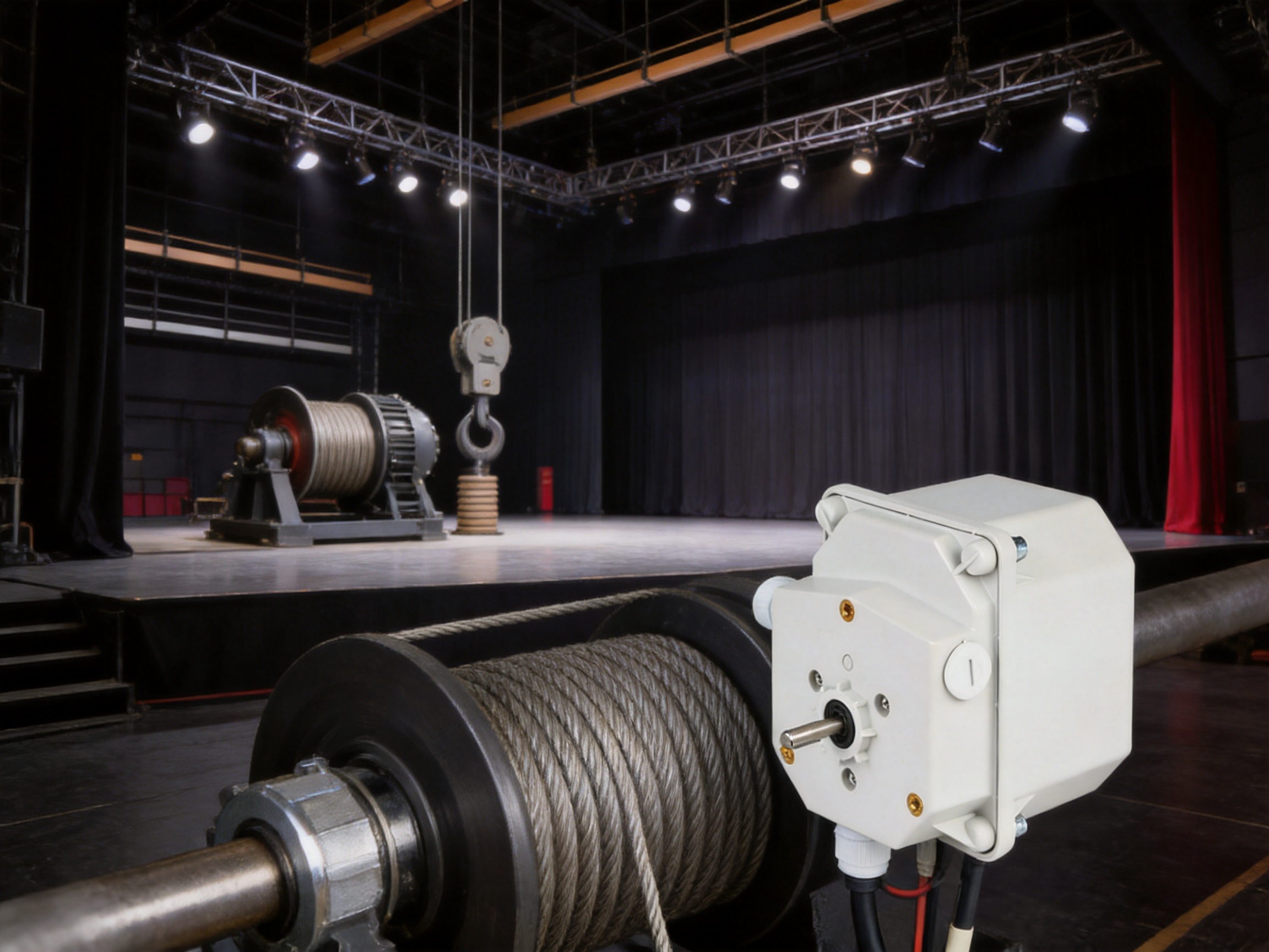
Although stage machinery is a primary application, the operating principle of a Gear Limit Switch is useful in many industries.
In cranes and hoisting equipment, the switch can monitor lifting height, trolley travel, and winch rotation. It helps prevent over-winding, over-lowering, and travel beyond the permitted path. In bridge cranes and gantry cranes, reliable limit control is important for protecting loads, rails, drive systems, and surrounding structures.
In automated warehouses, rotary limit switches can monitor lifting platforms, stacker mechanisms, conveyor sections, and transfer equipment. Their mechanical feedback can supplement digital sensors and control software, especially in applications where a final physical limit is required.
In elevators and vertical transportation systems, position-control components help define travel boundaries and provide additional protection against excessive movement. Equipment designers must select products appropriate to the relevant safety requirements and installation environment.
In logistics conveyors and packaging machinery, the switch can detect the position of rotating shafts, gates, arms, or indexing mechanisms. Multiple cam settings may provide signals for stopping, sequencing, and fault detection.
Industrial production lines, assembly machines, port machinery, mining equipment, renewable-energy equipment, and construction machinery can also benefit from reliable rotary position control. Wherever movement is based on shaft rotation and must remain within defined mechanical limits, a Gear Limit Switch may provide a practical solution.
The performance of a precision limit switch begins with manufacturing discipline. A product may have a strong concept, but its real reliability depends on dimensional accuracy, material selection, assembly consistency, electrical quality, and inspection procedures.
Professional product development starts with a clear understanding of the equipment in which the switch will be installed. Engineers must evaluate input speed, shaft rotation, gear ratio, switching sequence, load conditions, environmental exposure, mounting requirements, and electrical interfaces.
Design teams can then select the appropriate gear arrangement, worm mechanism, cam geometry, housing structure, and microswitch configuration. Computer-aided design and engineering analysis help verify clearances, motion relationships, assembly access, and structural performance before production begins.
For customized projects, the manufacturer may adapt the output shaft, mounting holes, gear ratio, number of cam blocks, terminal arrangement, or housing details. This capability is valuable when the switch must integrate with an existing winch or a specialized stage machine.
Gears, worm components, shafts, cam discs, and mounting parts must be manufactured within controlled tolerances. Small dimensional deviations can affect backlash, switching repeatability, noise, and service life. Precision processing therefore plays a major role in the final quality of the assembly.
Manufacturing teams should control the condition of cutting tools, machining parameters, material batches, and inspection equipment. Critical dimensions can be verified using calibrated measuring instruments. Components that do not meet the specified requirements should be removed from the assembly process rather than corrected informally.
The protective housing must provide mechanical support, insulation, and environmental protection. Flame-retardant materials are especially important in equipment associated with electrical control and public venues. The enclosure should maintain its shape under normal operating temperatures and resist cracking during installation or service.
Internal components require suitable materials and surface treatments to withstand repeated movement. Gear surfaces, shafts, and cam interfaces must be selected for wear resistance and stable operation. Proper lubrication practices are also important for reducing friction and protecting the transmission system.
Assembly quality directly affects the alignment of the gear train and cam mechanism. Technicians must install gears, shafts, worm components, microswitches, and terminals in the correct sequence. Excessive clearance may cause backlash, while insufficient clearance may increase friction or restrict movement.
A professional production line uses defined assembly procedures, work instructions, torque requirements, and inspection checkpoints. These controls reduce variation between individual products. They also make it easier to trace the cause of a problem if a product is returned for analysis.
Every microswitch circuit should be checked for correct operation, terminal integrity, insulation condition, and contact response. Electrical inspection verifies that the device can deliver the intended signal when the cam reaches each programmed position.
Terminal screws, conductors, and internal connections must be secured correctly. Poor connections can produce intermittent faults that are difficult to identify in the field. Systematic electrical testing helps prevent such problems before shipment.
Mechanical testing should confirm that the input shaft rotates smoothly, the gear train transfers motion correctly, the cam discs move as intended, and the microswitches actuate at the specified positions. Testing may include repeated cycles to evaluate consistency.
Where required, manufacturers can test operation at representative shaft speeds. The product is designed to support driving speeds up to approximately 8.5 revolutions per minute, but the correct operating range must always be confirmed for the selected model and application.
Before delivery, finished products should undergo a final inspection covering appearance, dimensions, adjustment range, terminal layout, switching behavior, and packaging. Product identification and inspection records help customers maintain traceability.
Clear technical documentation should explain installation, wiring, adjustment, operating limitations, and maintenance. Good documentation reduces commissioning errors and helps technicians service the product safely.
RenteZhihe (JiangSu) Equipment Technology Co., Ltd. specializes in stage machinery, performance equipment, industrial machinery, and intelligent control systems. Its capabilities extend beyond the manufacture of an individual component. The company integrates research and development, production, installation, commissioning, and technical services, allowing it to understand the complete operating environment in which a Gear Limit Switch is used.
The company operates two modern production workshops covering approximately 13,000 square meters, together with a 7,000-square-meter office and research and development center. This industrial foundation supports coordinated engineering, manufacturing, quality management, and project service activities.
Since its establishment in 2012, the company has developed experience in motion-control applications for stage systems, lifting equipment, industrial automation, and intelligent machinery. This application knowledge helps engineers evaluate a limit switch not as an isolated catalog item, but as part of a complete equipment system.
The company’s high-tech enterprise background supports continued investment in product development and precision manufacturing. Its technical teams can work with customers to understand equipment movement, identify required control points, and recommend an appropriate mechanical and electrical configuration.
Another important strength is customization. Different winches and lifting systems may have different shaft diameters, mounting patterns, rotation ranges, travel speeds, environmental conditions, and switching requirements. A professional supplier can provide a custom Gear Limit Switch configuration instead of forcing the customer to redesign the entire machine around a standard product.
Customization may involve the transmission ratio, number of microswitches, cam arrangement, output shaft design, mounting interface, terminal configuration, or housing details. The purpose is not customization for its own sake. It is to achieve reliable compatibility between the switch and the equipment.
Engineering support also extends to installation and commissioning. A supplier with experience in stage machinery can assist with setting the upper and lower limits, verifying slow-down points, checking emergency stop behavior, and coordinating the switch with the drive and control system. This reduces the risk of incorrect field adjustment.
The first step is to identify how many shaft rotations correspond to the full equipment travel. This information depends on the drum diameter, cable arrangement, screw mechanism, gearbox, or other transmission components. The selected gear ratio must provide adequate adjustment range without causing the cam mechanism to move too quickly or too slowly.
The shaft speed should be compared with the rated operating capability of the switch. A system that operates near the maximum speed requires careful evaluation of acceleration, deceleration, vibration, and switching frequency. The stated maximum driving speed of approximately 8.5 revolutions per minute should not be treated as a universal value for every configuration. Application conditions and product specifications must be reviewed together.
Determine how many independent control points are required. A basic system may need only upper and lower limits. A more advanced stage machine may require slow-down, stop, confirmation, reverse, alarm, and emergency positions.
The number and type of electrical contacts must match the control circuit. Engineers should confirm whether the application requires normally open contacts, normally closed contacts, changeover contacts, or a combination of these arrangements.
Check the output shaft dimensions, keyway or coupling requirements, mounting holes, installation orientation, available space, and shaft alignment. Misalignment can produce excessive side loading, vibration, and premature wear.
The switch should be mounted on a rigid support, and the connection should allow the equipment shaft to rotate without imposing unintended forces on the switch. Installation instructions should be followed carefully.
Indoor theaters may have relatively controlled environments, while outdoor stages, industrial plants, ports, mines, and construction sites may expose the device to dust, moisture, temperature changes, vibration, or corrosive substances. The housing, sealing, materials, and protection rating should be appropriate for the actual conditions.
In areas where water spray, condensation, or corrosive vapors are present, additional enclosure protection or installation measures may be required. Environmental compatibility is as important as mechanical and electrical compatibility.
Choose a design that permits practical inspection and adjustment. Technicians should be able to verify the cam positions, inspect the terminals, and confirm microswitch operation without unnecessary disassembly.
The equipment maintenance plan should include periodic checks of shaft coupling, mounting bolts, gear movement, electrical terminals, and limit positions. The frequency depends on operating cycles, load conditions, environmental exposure, and the consequences of failure.
Before installation, technicians should compare the product specifications with the equipment design. Confirm the required rotation direction, shaft relationship, gear ratio, switching sequence, and contact arrangement. The switch should not be installed solely by matching its external dimensions.
The mechanical connection must be aligned carefully. A flexible coupling may be used where appropriate, but it should not introduce excessive backlash. The mounting bracket must be rigid enough to prevent the switch from shifting during operation.
After mechanical installation, the equipment should be moved slowly and manually or through a controlled commissioning mode. Each cam should be adjusted to the intended position, and the corresponding microswitch signal should be checked independently. Technicians should verify that the switch changes state in the correct direction and that the control system responds as expected.
Slow-down points should be tested before final stop points. The equipment should decelerate sufficiently to avoid excessive impact at the limit. Normal limits and secondary safety limits should be clearly distinguished and documented.
After adjustment, the system should be cycled repeatedly. Repeated testing can reveal backlash, loose connections, incorrect rotation direction, or a cam setting that shifts under vibration. Final settings should be recorded in the equipment maintenance documentation.
Commissioning should also verify the interaction between the Gear Limit Switch, motor controller, brake, emergency stop circuit, PLC, and operator interface. A limit switch should not be considered correctly installed until the complete control sequence has been tested.
Regular maintenance helps preserve the accuracy and reliability of the Gear Limit Switch. The maintenance team should inspect the housing for cracks, deformation, or signs of impact. Cable glands and terminal covers should remain secure, particularly in dusty or humid environments.
The shaft connection should be checked for looseness, misalignment, and excessive wear. If the coupling becomes loose, the switch may no longer correspond accurately to the actual equipment position. This can create a dangerous difference between the indicated limit and the physical travel boundary.
Cam settings should be verified periodically, especially after major maintenance, gearbox replacement, cable replacement, or structural modification. Any change to the equipment transmission can alter the relationship between shaft rotation and travel distance.
Electrical terminals should be inspected for looseness, corrosion, discoloration, or heat damage. Microswitch operation can be checked using suitable test equipment while rotating the shaft through the relevant positions.
Operators should avoid prolonged overload operation. Excessive mechanical loading, impact, or abnormal vibration can shorten the life of the transmission system. If unusual noise, inconsistent switching, or unexpected movement is observed, the equipment should be stopped and inspected before returning to service.
Replacement parts should be compatible with the original product configuration. In safety-related applications, unapproved substitutions can change electrical characteristics or mechanical timing. Technical support should be consulted when a replacement microswitch, gear component, or cam assembly is required.
The most important function of a Gear Limit Switch is to prevent equipment from moving beyond its intended boundaries. This protection can reduce the likelihood of over-winding, over-lowering, collisions, mechanical interference, and damage to suspended loads.
It also helps reduce stress on motors, brakes, gearboxes, wire ropes, drums, guide rails, and support structures. When equipment stops at the correct point, the mechanical system avoids unnecessary impacts and repeated overload conditions.
Accurate limits support safer operation for personnel as well. In stage environments, technicians may work near moving equipment during setup and maintenance. Reliable stopping positions reduce the risk that a batten, truss, lift, or curtain will travel unexpectedly into an occupied area.
Safety depends on the complete system, not on one component alone. The Gear Limit Switch should be integrated with suitable emergency stops, brakes, overload protection, control logic, guarding, inspection procedures, and operator training. Correct adjustment and regular testing are essential to maintain its protective function.
A specialized manufacturer understands that a Gear Limit Switch is a safety-related motion-control component rather than a generic electrical accessory. Its performance must be evaluated in relation to the winch, lift, hoist, gearbox, cable system, drive controller, and operating environment.
Professional manufacturing provides several advantages. First, it supports consistent mechanical tolerances and stable gear engagement. Second, it allows the manufacturer to verify electrical and mechanical performance through structured testing. Third, it gives customers access to engineering assistance when standard products require adaptation.
Specialized suppliers can also support the complete project lifecycle. During design, they can help identify the required ratio and switching points. During production, they can coordinate product configuration with the equipment builder. During installation, they can assist with adjustment and commissioning. During operation, they can provide maintenance guidance and technical support.
RenteZhihe combines product manufacturing with broader stage machinery and intelligent-system capabilities. This combination allows the company to address both the individual Gear Limit Switch and the larger motion-control application. Customers can obtain a component designed with practical knowledge of theaters, performance venues, lifting systems, and industrial automation.
The company’s integrated services include design, manufacturing, installation, commissioning, operation support, and maintenance. This approach helps reduce the communication gaps that can occur when a component supplier, machinery builder, installer, and control-system integrator work without sufficient coordination.
Automation is becoming more connected, but mechanical protection remains important. Future stage systems will likely combine Gear Limit Switches with encoders, programmable controllers, variable frequency drives, network communication, condition monitoring, and digital maintenance records.
These technologies can improve operational efficiency and provide more detailed information about equipment status. However, the basic need for a dependable physical limit remains. A mechanical switch offers a direct relationship between shaft movement and limit actuation, independent of many software or communication functions.
Future products may emphasize smaller dimensions, improved environmental protection, greater adjustment flexibility, higher switching endurance, and easier integration with intelligent control systems. Manufacturers with experience in both mechanical transmission and automation will be well positioned to develop these solutions.
The most effective systems will use layered protection. Normal movement may be managed by a PLC and drive controller, position may be monitored by an encoder, and final travel protection may be provided by a mechanically actuated Gear Limit Switch. This combination creates redundancy and improves the overall safety margin.
A Gear Limit Switch detects the rotational position of a shaft and sends electrical signals when the connected equipment reaches preset positions. It can be used to stop, slow, reverse, or provide an alarm for stage winches, lifts, hoists, and other automated machinery.
A standard limit switch is usually actuated by direct contact with a nearby moving part. A Gear Limit Switch uses a gear reduction mechanism and adjustable cams to monitor shaft rotation over a longer travel range. It is therefore more suitable for equipment involving multiple shaft rotations and several independently adjustable control points.
Yes. The multiple independent cam and microswitch structure allows several actuation points to be set. These points may be used for slow-down, normal stop, secondary safety stop, reverse, confirmation, or alarm functions.
Yes. The worm-wheel cam structure is designed to make field adjustment practical. Technicians can calibrate the cam positions according to the actual travel of the equipment. Adjustment should be performed by qualified personnel with the machinery isolated or placed in a controlled commissioning mode.
Typical applications include stage winches, pile winders, battens, lighting trusses, stage lifts, fire curtains, electric hoists, cranes, elevators, conveyors, automated warehouses, packaging machinery, logistics equipment, port machinery, mining equipment, and industrial production lines.
Important factors include shaft rotation, travel range, operating speed, gear reduction ratio, number of switching points, contact arrangement, output shaft dimensions, mounting pattern, environmental conditions, protection requirements, mechanical durability, and electrical compatibility.
Not necessarily. It is generally used as part of a complete motion-control system. A PLC or encoder may manage normal operation and provide detailed position information, while the Gear Limit Switch supplies independent mechanical limit protection. The appropriate architecture depends on the equipment design and applicable safety requirements.
The described design supports driving speeds of up to approximately 8.5 revolutions per minute. The actual permissible speed depends on the selected configuration, operating conditions, switching frequency, and manufacturer specifications. Engineers should confirm the exact rating before final selection.
Service life can be extended by selecting the correct model, maintaining accurate shaft alignment, avoiding overload and excessive vibration, inspecting terminals and couplings, checking cam settings regularly, and following the manufacturer’s installation and maintenance instructions.
Professional manufacturing ensures that gears, cams, shafts, housings, and microswitches are produced and assembled consistently. It also provides functional testing, customization capability, technical documentation, and engineering support. These factors are especially important when the product is used in stage machinery or other safety-related motion systems.
The Gear Limit Switch is a compact but essential component for accurate and safe motion control. Its planetary gear transmission, self-locking worm, adjustable cam structure, and independent microswitches provide reliable position detection for equipment that must move along defined travel paths.
Compared with basic direct-contact limit switches, it offers greater repeatability, multiple independent control points, convenient adjustment, compact construction, strong carrying capacity, and dependable operation across long travel ranges. These advantages make it particularly suitable for stage winches, pile winders, lifts, battens, lighting trusses, fire curtains, hoists, cranes, and industrial automation systems.
Product quality depends on more than the visible enclosure. Precision components, controlled assembly, reliable electrical connections, functional testing, accurate adjustment, and professional technical support all contribute to safe performance. A manufacturer with experience in stage machinery and intelligent control systems can provide more than a standard component. It can help customers select, customize, install, commission, and maintain a complete motion-control solution.
With integrated research and development, modern production facilities, technical service capabilities, and customization experience, RenteZhihe is positioned to support customers seeking reliable Rotary Limit Switch and Gear Limit Switch solutions. When correctly selected and maintained, the product provides an important mechanical safeguard that helps stage and industrial equipment operate smoothly, accurately, and safely over the long term.
1. Industrial Automation Motion-Control Principles, technical reference material on mechanical travel limitation and position feedback.
2. Stage Machinery Safety and Operation Practices, professional guidance for powered theater equipment and suspended loads.
3. Mechanical Power Transmission Fundamentals, reference material on planetary gears, worm drives, cam mechanisms, and backlash control.
4. Electrical Control Components and Microswitch Applications, engineering reference for contact arrangements, switching circuits, and control-system integration.
5. Industrial Equipment Maintenance Planning, technical guidance on inspection, commissioning, preventive maintenance, and service-life management.
6. RenteZhihe Product Engineering and Manufacturing Information, technical product data for Gear Limit Switches and stage automation equipment.
We specialize in delivering advanced stage machinery, rigging systems and intelligent control solutions for performance spaces worldwide.

No. 111 Runfeng Road, Hailing District, Taizhou City, Jiangsu Province, China

rtstage@163.com

+86-139 1771 1698

+86-139 1771 1698
rtstage@163.com
 中文简体
 English
 русский
 Français
 Español
 عربى